Aerial construction
Shopping list
- N-type connector, 50 ohm, flange mounting
- 1.5 mm² (cross-sectional area) copper cable, e.g. from a piece of heavy three-wire mains cable
- countersunk screws, 10 mm long, maximum thread diameter 3 mm
- four nuts to fit
- washers, approx. 20
Apart from the router and the antenna cable, which you can find in any good electrical goods shop, the parts required for the tin-can antenna come into the pocket-money range: four securing screws with countersunk heads and matching washers and nuts, the 50 ohm N-type socket (not TNC) with a flange, and left-over cable from an electrical installation. The insulated wire should be not less than one millimetre in diameter, and it must fit into the sleeve of the N-type socket. Threaded N-type sockets with large securing nuts are of limited suitability for a tin-can antenna, since by projecting inside the can they interfere with the electromagnetic wave and reduce gain.
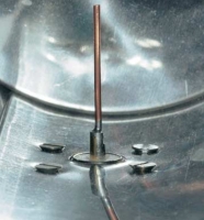
![]() Nothing other than the coupling pin should project into the interior of the can. Otherwise, scattering and reflections will cause losses. This was is why used screws with countersunk heads.
Five drilled holes are required for the N-type socket used: four small ones for the screws, and a big one for the coupling. The latter should correspond as precisely as possible with the external diameter of the white insulator of the N-type socket - ten millimetres for the socket we used - so that the outer metal conductor lies as closely as possible against the metal plate, as shown in the illustration, and projects as little as possible into the can.
Nothing other than the coupling pin should project into the interior of the can. Otherwise, scattering and reflections will cause losses. This was is why used screws with countersunk heads.
Five drilled holes are required for the N-type socket used: four small ones for the screws, and a big one for the coupling. The latter should correspond as precisely as possible with the external diameter of the white insulator of the N-type socket - ten millimetres for the socket we used - so that the outer metal conductor lies as closely as possible against the metal plate, as shown in the illustration, and projects as little as possible into the can.
Drilling into the thin sheet metal is best done by the boring-out method or using a sheet metal punch: first, punch as precisely as possible the spot where the coupling pin will be positioned. Take the distance to the bottom inside the can from the. When making the measurement, remember to take account of the breadth of the fold at the bottom of the can.
Drill the first hole with the smallest possible drill (2 mm). You can make this easier by punching the metal with a hammer and nail. If you use a high rotational speed and little pressure, the drill is very unlikely to tear into the thin sheet metal. Increase the diameter in approximately 2 mm steps until the required size is achieved, or until the bolt size of the metal punch is reached. The last step, if required, is to finish off with a round file.
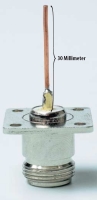
![]() The copper-wire coupling pin is attached using a soldering iron. It's connected to the inner conductor of the socket, and then cut to the right length.
We used a straightened copper wire from a regular, three-wire electrical installation cable as a coupling pin. This has to be soldered to the inner conductor of the N-type socket. It's much easier to do the soldering first and then cut the wire to length, instead of cutting it to length to start with. The length, including the outward projecting part of the internal conductor of the socket, must be a quarter of the wavelength of the operating frequency, in this case 30 millimetres.
The copper-wire coupling pin is attached using a soldering iron. It's connected to the inner conductor of the socket, and then cut to the right length.
We used a straightened copper wire from a regular, three-wire electrical installation cable as a coupling pin. This has to be soldered to the inner conductor of the N-type socket. It's much easier to do the soldering first and then cut the wire to length, instead of cutting it to length to start with. The length, including the outward projecting part of the internal conductor of the socket, must be a quarter of the wavelength of the operating frequency, in this case 30 millimetres.
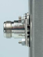
![]() The metal collar and the can wall should end on the same level. Two washers ensure the correct distance between the flange and the sheet metal.
Washers on the outside, between the metal of the can and the N-type socket, ensure the correct distance. The metal cylinder around the white dielectric of the socket should stop precisely at the level of the can metal and not project into the can. We used two washers on each screw. The four screws also provide additional electrical contact with the antenna can. If the can is painted, or coated in some other way, remove the coating around the drilled holes to ensure electrical conductivity. If the coupling hole ends up being too large so that there is insufficient electrical contact with the can, you can rectify things by putting crumpled aluminium foil between the flange of the socket and the can.
The metal collar and the can wall should end on the same level. Two washers ensure the correct distance between the flange and the sheet metal.
Washers on the outside, between the metal of the can and the N-type socket, ensure the correct distance. The metal cylinder around the white dielectric of the socket should stop precisely at the level of the can metal and not project into the can. We used two washers on each screw. The four screws also provide additional electrical contact with the antenna can. If the can is painted, or coated in some other way, remove the coating around the drilled holes to ensure electrical conductivity. If the coupling hole ends up being too large so that there is insufficient electrical contact with the can, you can rectify things by putting crumpled aluminium foil between the flange of the socket and the can.
Throughout the work, ensure that the can stays round, otherwise the directional effect will be degraded.
Don't put any additional screws through the wall in order to assemble the finished antenna to a holder, because their heads would form internal sources of interference. For indoor use, it's usually sufficient to fasten the antenna to a shelf or shelf bracket with gaffer tape, adhesive tape or large cable ties. For outdoor mounting, gutter clamps or coated, corrosion-resistant perforated ribbon are more weather-resistant.
Lightning protection
If the antenna will be positioned on a roof, you also have to think about lightning protection. Only if the mast is correctly connected to the lightning protection system will your insurer pay in the event of damage to the house. Mounting it on a house wall is less problematic: the antenna need only hang more than two metres below the eaves and a maximum of one metre away from the wall. This can be easily done using a satellite-dish wall bracket. In many cases, however, it is sufficient to position the antenna indoors at a window, although modern coated windows do degrade performance somewhat.


![Kernel Log: Coming in 3.10 (Part 3) [--] Infrastructure](/imgs/43/1/0/4/2/6/7/2/comingin310_4_kicker-4977194bfb0de0d7.png)

![Kernel Log: Coming in 3.10 (Part 3) [--] Infrastructure](/imgs/43/1/0/4/2/3/2/3/comingin310_3_kicker-151cd7b9e9660f05.png)